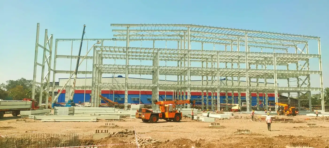
PEB Erection & Installation
Structured, safe, and precision-driven erection process ensuring strong and reliable pre-engineered building performance.
Structured, safe, and precision-driven erection process ensuring strong and reliable pre-engineered building performance.
Establish construction logistics for the initial erection survey:
This method statement outlines the procedures, safety measures, and quality standards for the specified work. The supervisor is responsible for reading this statement to the site personnel involved in the task.
To ensure everyone understands, the contents will be translated into the languages spoken by the workers as they are read aloud.
CRITICAL DIRECTIVE: Erection must start from the braced bay.
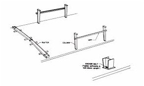
Attach the flange brace angle, bracket, and clips to the main column. Erect the main column in the wind-braced bay and promptly tighten the anchor bolts. Once the main column is secured with a nut and lock nut, ensure it is plumb. If there is a gap between the bottom of the base plate and the top of the R.C.C. column, insert M.S. shim plates. After confirming the column is plumb, retighten the nut and install temporary bracing using a minimum 16 mm diameter M.S. wire rope.
Note: Release the crane only after you have installed the temporary bracing (guy ropes) and tightened the bolts completely.
Follow the same procedure from Step 1 to erect the second adjacent column. Immediately secure the eave strut between the two columns. Next, install the girts and flange braces.
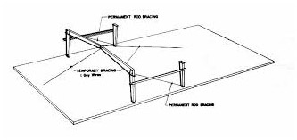
Connect both braces using hillside washers and nuts. Once in place, ensure the braced rod is fully tightened.
The hillside washer assembly, along with the wall bracing, is illustrated in detail in the figure below.
Note: Same procedure has to be followed in opposite grid for erecting column and bracing.
Secure as many clips and flange braces as possible before raising the rafter to minimize assembly time. It's much easier to put these components together on the ground than in the air.
As you assemble each grid frame, install and tighten all connection bolts.
Refer to the primary frame drawing for the correct flange brace locations. Attach the flange brace to one side of the roof rafter assembly while it’s still on the ground, and then connect the brace to the opposite side once the rafter assembly is lifted into a vertical position.
Lift the rafter using cranes and secure it with appropriate guy ropes. At the rafter's ends, use temporary bracing from the ground to connect it to the columns.
Keep the rafter steady until it is firmly bolted to the columns, and install temporary bracing to support the assembled ridge frame. Use guy ropes made of at least 16mm diameter M.S. steel for the bracing. Tension the bracing with a 1-meter turnbuckle attached to an R.C.C. column.
Ensure that the temporary bracing is tightened evenly on both sides.
Warning: Temporary bracing must be installed at all the haunches, which are the connection plates of the rafters.
Before installing the second rafter, first erect the third main column following the procedure outlined in Step 1. Once the third main column is in place, raise the second rafter with a crane and secure it until it is bolted to the columns.
Next, bolt all purlins, flange braces, and sag rods into position.
Install the roof brace rods using hillside washers and nuts, ensuring that each brace rod is fully tightened. Then, align and square the braced bay, and add temporary bracing at the haunches.
Do not proceed with any further construction until Steps 3 and 4 are complete. The crane should only be released after these steps are finished.
After aligning the brace bay, a civil contractor must grout the gap between the top of the R.C.C. column and the bottom of the base plate using CONVEXTRA (GP-2 non-shrinkage grouting material) immediately.
Note: The space between the top of the R.C.C. column and the bottom of the base plate should not exceed 25mm.
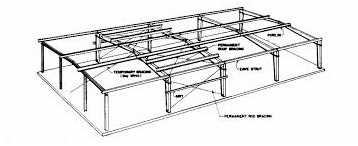
To continue erecting the remaining frames in each braced bay, as illustrated in Fig. 7, follow the procedures outlined in Steps 3 and 4 for installing temporary bracing. Remove the temporary bracing only after the sheeting is fully completed.
Here are the steps for installing temporary bracing in a ground system arrangement:
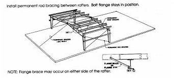
On the opposite side of the rafter, the ground rope is attached to the building's column (as shown in Figure 8) to ensure that there are no obstacles during the construction process.
Once the main frame is erected, we will install the bracings. Use spanners to tighten all the components to the specified torque.
Align the building with the first bracing bay between grid lines 1 and 2, as well as between grid lines 8 and 9.
To continue with the setup, please follow steps 1 through 10 consecutively.
Verify the alignment, leveling, and tightening of the structure from grid 1 to grid 10.
Adjust the rake angles of the side wall and end wall eave struts from grid 1 to 10, ensuring that the valley gutter is included in both side walls.
Move the sheets from the storage yard to the installation site according to the approved drawings, and begin the roof and wall sheeting as specified in the approved erection plans.
Begin the roof and wall sheeting work from grid lines 1 to 10, following the approved erection drawings and the part marks indicated in those drawings.
Shift the DSP material from material stock yard to erection place.
Fix the DSPs as per approved drawings and part mark given in the drawings using suitable crane and rope pulley.
Nuts & Bolts use the DSP with valley gutter and fix the supports in wall as per drawings.
Note:– Clean the installed Hi-Rib sheet at the end of each day.